Rectifier Module
Schematic
The rectifier portion of this module is composed of:
· 1% metal film ¼ watt resistors
· LT 1007 operational amplifiers
· IN916C Diodes

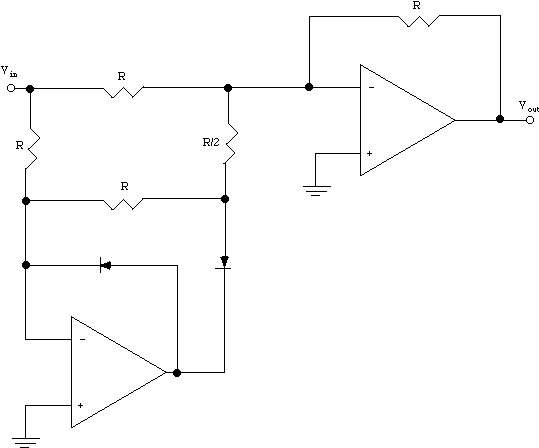
The schematic of a typical Full-Wave Rectifier is presented below. To enlarge the schematic, click on it.
This schematic gives an example of a circuit for a Full-Wave Rectifier. The circuit shown here gives a positive output equal to the magnitude of the input signal. The output signal is full-wave rectified.
The circuit that is implemented in the lab is discussed here. The HP/Rectifier module consists of two parts, a high-pass filter and a rectifier. The input signal (from the EMG amplifier) can be high-pass filtered using the fourth-order Butterworth filter (Frequency Devices-711H4B; Frequency Devices, Haverhill, MA) with a cut-off frequency of 5Hz. The HP/Rectifier panel has two outputs, normal and rectified. The polarity of the full-wave rectified signal is selected using the rectifier (+/-) switch. (TA EMG is positively rectified; GS EMG is negatively rectified).
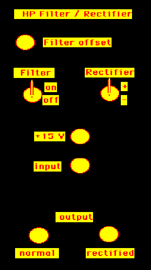
Front Panel
Inputs:
One input (V1) is applied by the BNC connectors on the front panel.
Outputs:
Two output channels are provided on the output. One of the output is for obtaining the normal EMG signal (not rectified). The other output channel is for the rectified EMG signal. There is also a +15 Volt supply available from the front panel of the module.
Input Selection:
- Filter
- On: switch is connected to the front panel. Filters the EMG signal.
- Off: switch is connected to the front panel. Does not filter the EMG signal.
- Rectifier
- +: switch is connected to the front panel. Rectifies the EMG signal.
- -: switch is connected to the front panel. Does not rectify the EMG signal.
Filter Offset
The filter offset can be manually controlled by the user.
Circuit Diagram
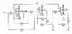
Rectifier Schematic
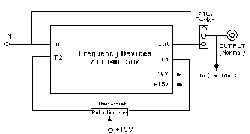
High-Pass Filter Schematic
Operation
The EMG signal is input to the circuit via a BNC connector on the front panel of the module. The rectified or normal signals can obtained from the two parallel output channels. The can be filtered and rectified or a combination of the two via the filter and rectifier switches on the front panel.
List of Components
· 3 LT1007 Operational Amplifier
· Dielectric Capacitors
· +/- 10% Resistors
· 2 1N916C Signal Diodes
Functional Specifications
This module requires +/- 15 Volt power supply to operate.
Please send any questions regarding the information here to:


